About Us

How to determine Bearing Capacity of soil from SPT Value

Bearing Capacity of soil from SPT Value 

Bearing Capacity of Soil: Bearing Capacity is the capacity of soil to support the loads applied to the ground. Here we will discuss how to determine bearing capacity of soil from SPT value.


Why Bearing Capacity is Important?

Bearing capacity is important due to the following reasons:

1. Structural Stability

Prevents Settlement:

Adequate bearing capacity ensures that the foundation does not settle too much under the weight of the structure. Excessive settlement can lead to uneven floors, cracks in walls, and other basic issues.

Avoids Shear Failure:

If the soil's bearing capacity is exceeded, the ground can shear and collapse, leading to disastrous structural disappointment.

2. Safety

Ensures load transfer:

Proper foundation design based on soil bearing capacity guarantees that loads from the structure are viably exchanged to the ground, keeping up the integrity and safety of the building.

Mitigates the Risk of Collapse:

Understanding and designing for the proper bearing capacity helps prevent the chance of sudden collapse due to soil disappointment.

3. Cost Effectiveness

Optimizes Foundation Design:

Knowing the bearing capacity allows engineers to design the most efficient and cost-effective foundation. Overdesigning (utilizing too many expansive establishments) can be costly, whereas underdesigning can lead to structural issues and expensive repairs.

Reduces construction costs:

Accurate evaluation of bearing capacity can lead to the selection of appropriate foundation types and sizes, reducing unnecessary material and labor costs.

4. Life span of the structure

Guarantees Strength:

Establishments planned with legitimate thought of bearing capacity contribute to the long-term strength and benefit life of the structure.

Minimizes Upkeep:

A well-designed establishment decreases the need for visit support and repairs due to foundation-related issues.

Plans for Future Loads:

Knowing the bearing capacity permits the planning of establishments that can accommodate future extensions or extra loads without compromising structural integrity.


bearing capacity of soil from SPT value

How to Determine Bearing Capacity of Soil From SPT Value: The Standard Penetration Test (SPT) is an in-situ test which is carried out in borehole to determine soil bearing capacity . This test measured the resistance of the soil strata to the penetration undergone. SPT value can determined by counting the number of blow required to penetrate the last 12in (300 mm approx.) of a 18 in.( 450 mm approx.) sampler. After getting this value we can easily determine the bearing capacity of soil by following formulas:

Meyerhof's Formula:

For footing width 4 feet or less:
Qa= (N/4) / K

For footing width greater than 4 feet:
Qa = ( N/6) [( B+1)/B]2 / K

Bowle's Equation:

For footing width 4 feet or less: 
Qa= (N /2.5) /K

For footing width greater than 4 feet: 
Qa= (N/4) [( B+1)/ B]2 / K. 

Where, 
Qa= Allowable bearing capacity of soil in, kip/sft   
= SPT Number Below the Footing
= Width of footing in foot 
D = Depth from ground level to the bottom of footing,  in foot

K1+ 0.33( D/B) which will be less than or equal to 1.33

Curing of Concrete slab

Curing of Concrete slab

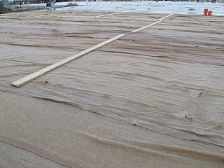
Curing: Curing of concrete is a process by which fresh wet concrete is allowed to complete its reaction to attained its desire strength. By this method concrete is protected against loss of moisture required for hydration and kept within the recommended temperature range. 


Curing of concrete

Curing of concrete


Necessity of Curing of Concrete slab:

1) To enhance hydration of concrete to achieve desire strength.

2) Well cured concrete has minimum thermal, plastic and drying shrinkage crack which make concrete more water, tight results durable concrete.

3) In-adequate curing results weak and dusty surface of concrete, results a poor abrasion resistance.

Types of Building Foundations

 Types of Building Foundations 

Foundations are basically of two (02) types: 

1) Shallow Foundation
2) Deep Foundation
Types of Building Foundations 

1) Shallow Foundation: According to Terzaghi, if the depth of foundation is less than or equal to its width, then it is called a Shallow Foundation. This type of foundation transfer building load to the earth very near to the surface.
You may like this: Clear Cover of Concrete

Shallow Foundations are:

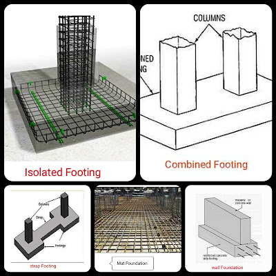
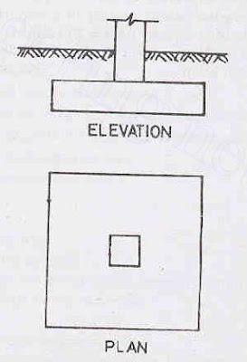
i) Isolated Footing: This is the most common type of foundation used for building construction and also most economical one. They are most commonly square and rectangular is size.

Types of Building Foundations


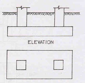
ii) Combined Footing: Combined footing support more than one column in a row. Combined footings are constructed when two or more columns are close enough and their isolated footing overlaps one-another.

Types of Building Foundations


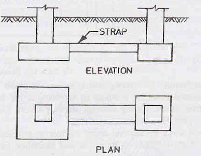
iii) Strap Footing: A strap footing consists of two isolated footings connected with a structural strap or a lever. The strap connects the two footing such that they behave as one unit. The strap simply act as a connected beam and does not take any soil reaction. 

Types of Building Foundations


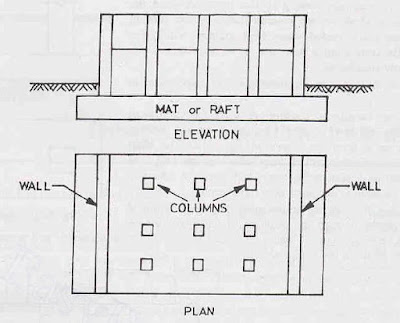
iv) Mat or Raft Foundation: A mat or a raft is a large slab supporting a number of columns and wall under the entire or large part of a structure. Mat foundation required when the allowable soil pressure is low or where the columns or walls are so closed that individual footings overlap or touch each-other.

You may like this: Slump Test of Concrete


Types of Building Foundations


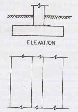
v) Wall Footing: This type of foundation runs along the direction of the wall and helps to transmit the load of the wall into the ground.


Types of Building Foundations


2) Deep Foundation: According to Tarzaghi, if the depth of foundation is greater than its width. then it is called Deep Foundation. A deep foundation is generally much more expensive than a shallow foundation. 

You may like this: Workability of Concrete

Deep Foundations are:

It may be helpful for you:  Field test of cement

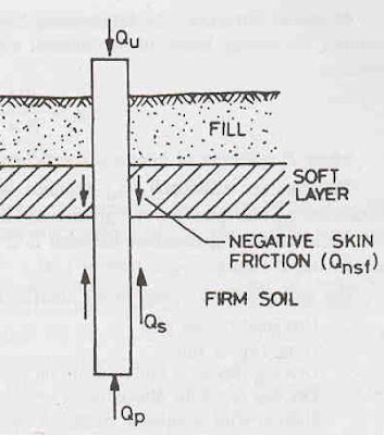
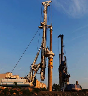
i) Pile Foundation : A pile is a slender structural member made of steel, concrete or wood. A pile is either driven into the soil or formed in-situ by excavating a hole a filling it with concrete.


Types of Building Foundations


ii) Pier Foundation: A pier is a large diameter concrete cylinder build in the ground. The difference between a drilled pier and a bored pile is basically of size.

Types of Building Foundations


iii) Well Foundation: A well foundation is similar to an open caisson. Well foundation can be constructed on a dry bed or after making a sand island.

Types of Building Foundations


Lapping Length of Reinforcement steel bars

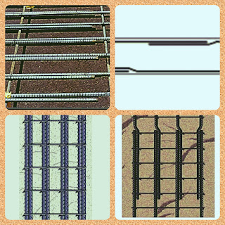
 Lapping: In RCC structure, placing of a single bar may not meet the required length of the section. So it becomes necessary to join two bars, to meet the desire length. To join two bars, one bar should overlap another and it is called lapping of bar and the length overlap each other is caller lap length or overlap length.

Lap length is different for different concrete section.

Lapping of Reinforcement


Calculation of Lapping Length:

Lapping is not permitted for reinforcement greater than No.11

lapping length for longitudinal reinforcements are as follows:

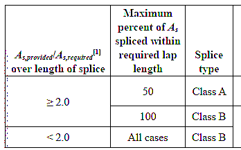
for Class A Splice: Lapping length will be the greater of 1.0Ld and 12 inch.

for Class B Splice: Lapping length will be the greater of 1.3 Ld and 12 inch.

 Lapping Length of Reinforcement

                 Table: Splice Type

* Here Ld is the development length.

Lapping length for Tension Reinforcement (same as Longitudinal Reinforcement):

for Class A splice: Lapping length will be the greater value of 
1.0 Ld and 12 inch.

for Class B splice: Lapping length will be the greater value of 1.3 Ld and 12 inch.

Here Ld is the development length.

Compression Lapping length of No.11 or smaller deformed bar
Shall be calculated as :

(a) for fy </= 60,000 psi lapping length is greater of 0.0005 fy*db and 12inch.

(b) for fy > 60,000 psi, lapping length is greater of (0.0009 fy-24)db and 12 inch.

Note: for fc'<3000 psi the length of lapping will be increased by one-third.

compression lapping should not permitted for bar greater than No.11 except permitted at code.

all informations are from ACI Code


Lapping in Reinforcement

Lapping in Reinforcement

Lapping in Reinforcement: Lapping length of reinforcement is one of the important term in RCC. It is a very confusing term, because most of the professional mixed up lapping length with development length or anchorage length.
Steel reinforcement has a limitation in length, usually it is 12.00 meter in length. So in case of  RCC structure, placing of a single bar may not meet the required length of the section and it becomes necessary to join two bars, to meet the desire length. To join two bars, one bar should overlap another and it is called lapping of bar and the length overlap each other is caller lap length or overlap length.
Lapping process

Lap length is different for different concrete section. You can find some thumbs formula i,e, 50d or 36d in many website but if you want to follow the ACI code you have the reading material below: 

Lapping in reinforcement

Lapping process

Calculation of Lapping Length:

Lapping is not permitted for reinforcement greater than No.11
lapping length for longitudinal reinforcements are as follows:
for Class A Splice: Lapping length will be the greater of 1.0Ld and 12 inch.

for Class B Splice: Lapping length will be the greater of 1.3 Ld and 12 inch.

Lapping in Reinforcement
 Table: Splice Type
* Here Ld is the development length.

Lapping length for Tension Reinforcement (same as Longitudinal Reinforcement):
for Class A splice: Lapping length will be the greater value of
1.0 Ld and 12 inch.
for Class B splice: Lapping length will be the greater value of 1.3 Ld and 12 inch.
Here Ld is the development length.

Compression Lapping length of No.11 or smaller deformed bar Shall be calculated as :
(a) for fy ≤60,000 psi lapping length is greater of 0.0005 fy*db and 12inch.
(b) for fy > 60,000 psi, lapping length is greater of (0.0009 fy-24)db and 12 inch.
Note: for fc'<3000 psi the length of lapping will be increased by one-third.
compression lapping should not permitted for bar greater than No.11 except permitted at code.

All informations are from ACI Code

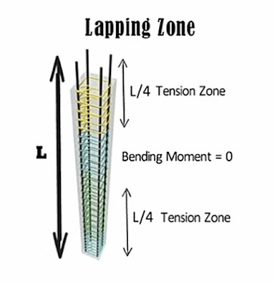
Lapping Zone: For column the lapping zone is middle portion of the column, because the L/4 distance from both support of the column experienced much tension and at the middle point the tension is zero. Since, middle portion experience less tension so it is safe to provide lapping in middle section.

Lapping in Reinforcement
Lapping Process

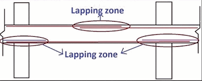
In case of beam, for top reinforcement mid section don't experience any negative moment so it is the safe zone for lapping. For bottom reinforcement, lapping is provided near the end of the beam or L/4 distance from column face.

Lapping in Reinforcement
Lapping Process

Frequently asked questions:


What is Lapping in reinforcement?

Ans: When placing of a single bar can not meet the required length of the section and it becomes necessary to join two bars, to meet the desire length. To join two bars, one bar should overlap another and it is called lapping of reinforcement.

Why is lapping used in reinforcement?

Ans: When placing of a single bar can not meet the required length of the section then lapping used to join two bars, to meet the desire length. 
Also lapping is required when bar diameter has to be change along the length.


Types of Building Foundation

Types of Building Foundations

Foundations are basically of two (02) types. Types of Building Foundation are as follows:  
 
1) Shallow Foundation
2) Deep Foundation

1) Shallow Foundation: According to Terzaghi, if the depth of foundation is less than or equal to its width, then it is called a Shallow Foundation. This type of foundation transfer building load to the earth very near to the surface.

You may like this: Clear Cover of Concrete

Shallow foundation are:

i) Isolated Footing: This is the most common type of foundation used for building construction and also most economical one. They are most commonly square and rectangular is size.

Types of Building Foundation


ii) Combined Footing: Combined footing support more than one column in a row. Combined footings are constructed when two or more columns are close enough and their isolated footing overlaps one-another.

Types of Building Foundation


iii) Strap Footing: A strap footing consists of two isolated footings connected with a structural strap or a lever. The strap connects the two footing such that they behave as one unit.The strap simply act as a connected beam and does not take any soil reaction. 

Types of Building Foundation


iv) Mat or Raft Foundation: A mat or a raft is a large slab supporting a number of columns and wall under the entire or large part of a structure. Mat foundation required when the allowable soil pressure is low or where the columns or walls are so closed that individual footings overlap or touch each-other.

You may like this: Slump Test of Concrete


Types of Building Foundation


v) Wall Footing: This type of foundation runs along the direction of the wall and helps to transmit the load of the wall into the ground.


Types of Building Foundation


2) Deep Foundation: According to Tarzaghi, if the depth of foundation is greater than its width. then it is called Deep Foundation. A deep foundation is generally much more expensive than a shallow foundation. 

You may like this: Workability of Concrete

Deep Foundations are:

It may be helpful for you:  Field test of cement

i) Pile Foundation : A pile is a slender structural member made of steel, concrete or wood.A pile is either driven into the soil or formed in-situ by excavating a hole a filling it with concrete.


Types of Building Foundation


ii) Pier Foundation: A pier is a large diameter concrete cylinder build in the ground. The difference between a drilled pier and a bored pile is basically of size.

Types of Building Foundation


iii) Well Foundation: A well foundation is similar to an open caisson. Well foundation can be constructed on a dry bed or after making a sand island.

Types of Building Foundation


Clear cover of Concrete As per ACI Code

Clear cover of Concrete As per ACI Code

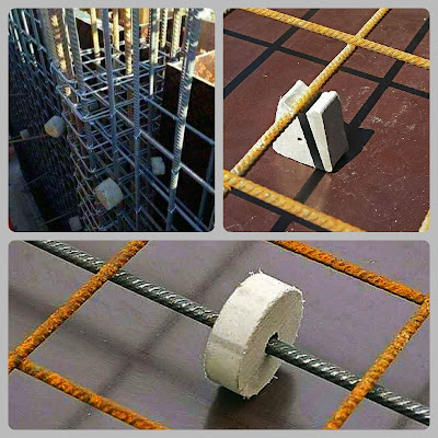
Clear Cover: Clear cover can be defined as the clear distance between the surface of the concrete and surface of the rebar.

Clear cover of Concrete As per ACI Code

Requirement of Clear Cover:
Clear cover is provided to protect the reinforcement from the phenomenon called corrosion and to provide fire resistance to bars embedded in concrete.
Clear Cover for  Different RCC Components:   
Clear Cover according to ACI 318 Code for plane concrete is-

 Description Clear Cover, inch
 Concrete cast against and permanently exposed to earth  
 3 
 Concrete exposed to earth or weather:
No. 06 through No.18 bar
No.05 bar and wire


 2
 1.5
 Concrete not exposed to weather or in contact with ground:
 Slabs, walls, joists:
No.14 and No.18 bars
No. 11 bars and smaller


 1.5
 0.75
Beams, Column

 1.5
 Shells, folded plate members
No.6 bars and larger
No.05 bars and smaller 


 0.75
 0.50

You may like this: Slump Test of Concrete

Types of Pile Foundation

Types of Pile Foundation 

Types of Pile Foundation can be classified based on (1) Material used (2) Mode of transfer of load (3) The use (4) Method of Installation (5) The Displacement of Soil.

Types of Pile Foundation


1) Classification Based on Material Used:
   
    i)       Steel Piles
    ii)      Concrete Piles
    iii)     Timber Piles
    iv)     Composite Piles.

2) Classification Based on the Mode of transfer of Load:

    i)      End Bearing Piles
    ii)     Friction Piles
    iii)    Combined end bearing and Friction Piles.

3)Types of Pile Foundation Classified Based on The Use:

    i)      Load Bearing Piles
    ii)     Compaction Piles
    iii)    Tension Piles
    iv)    Sheet Piles
    v)     Fender Piles
    vi)    Anchor Piles.

You may like this: Types of Shallow Foundation

4) Classification based on Method of Installation:

    i)     Driven Piles
    ii)    Driven and Cast-in-Situ Piles
    iii)   Bored and cast-in-Situ Piles
    iv)   Jacked Piles
    v)    Screw Piles.

5) Classification based on the Displacement of soil:

    i)    Displacement Piles.
    ii)   Non-Displacement Piles.

Properties of Sand

Sand is an important construction material, which plays an important role in engineering work. In construction work it is used as fine aggregate. 


Properties of good sand:

1) It should be clean and free from clay, silt etc. ( maximum allowable limit is 3-4%) 

2) It should be free from organic matters.

3) It should not contain any hygroscopic salts.

4) Grains should be sharp, coarse, angular and strong.

5) It should be completely inert.


Segregation of Concrete bangla (বাংলা)

সেগ্রিগেশনঃ কনক্রিটের হোমোজিনিয়াস ( সমসত্ত্ব) মিক্সিং থেকে এর উপাদানগুলো  আলাদা হয়ে যাওয়াকে কনক্রিটের সেগ্রিগেশন বলে।


কারণঃ সেগ্রিগেশনের কারণগুলো নিন্মরূপ-

১)  সেগ্রিগেশনের মূল কারণ হচ্ছে কনক্রিটের উপাদানগুলোর সাইজের ও স্পেসিফিক গ্রাভিটির পার্থক্য। পানি, সিমেন্ট ও পাথরের স্পেসিফিক গ্রাভিটি যথাক্রমে ০১, ৩.১৫ ও ২.৬-২.৭। স্বভাবতই স্পেসিফিক গ্রাভিটির পার্থক্যের  কারণে কনক্রিটের  হালকা উপাদানগুলো উপরে উঠে যেতে চায়, আর ভারী উপাদানগুলো নিচে পড়ে থাকতে চায়। যা সেগ্রিগেশন ঘটায়।
  
২) কনক্রিটের কাজে ব্যবহৃত পাথর/ খোয়ার গ্রেডেশন ঠিকমত না করা। 

৩) উচ্চ ওয়াটার-সিমেন্ট রেশিও। কনক্রিটিংয়ের সময় পানি বেশি ব্যবহার করলে সেগ্রিগেশন হয়। 
   
৪) কনক্রিটিংয়ের সময় ভাইব্রেশন বেশি  করলে সেগ্রিগেশন হয়।  

৫) কনক্রিটিংয়ের সময় কনক্রিট বেশি উচ্চতা থেকে ফেললে সেগ্রিগেশন হবে।

প্রতিরোধের উপায়ঃ

১) সেগ্রিগেশন প্রতিরোধের জন্য খোয়া/ পাথর, বালি  যথাযথভাবে গ্রেডেশন করতে হবে।

২) ওয়াটার-সিমেন্ট রেশিও যথাযথভাবে নিয়ন্ত্রণ করতে হবে।

৩)  কনক্রিট হ্যান্ডেলিং, ট্রান্সপোর্টিং, প্লেসিং এসব সময় যথাযথ যত্ন নিতে হবে। প্লেসিংয়ের সময় হাইট ১.৫ মিটারের বেশি যেন না হয় সে বিষয়ে খেয়াল রাখতে হবে।

৪) মেকানিকাল ভাইব্রেটর ব্যবহার করে কম্প্যাকশন করলে,  অবশ্যই অধিক যত্নবান হতে হবে।

৫) কনক্রিটের ভিস্কোসিটি বাড়াতে পারলে, তা সেগ্রিগেশন কমাতে সাহায্য করে। সেক্ষেত্রে ভিস্কোসিটি বাড়ানোর জন্য কিছু অ্যাডমিক্সার ব্যবহার করা যায়।   


Segregation of Concrete

Segregation: Segregation may be defined as the separation of the constituent materials of concrete from homogeneous mix.


Cause of segregation in concrete: Followings are the main cause of segregation

1) The root cause of segregation is difference in specific gravity and size of its constituent material.

2) Improper grading of aggregates.

3) Too much vibration during concreting.

4) Improper handling of aggregates.

5) High water cement ratio in concrete.Adding excess water while mixing concrete may lead to segregation.

6) Placing of concrete from a greater height, etc.

Prevention of Segregation:

1) Aggregate should be properly graded to prevent segregation.

2) Maintain proper water cement ratio.

3) At the time of placement care should be taken that the concrete is not poured from a height greater than 1.5 meter.

4) Care should be taken during compaction ( specially for compaction using mechanical vibrator).

5) To improve viscosity of concrete which prevent segregation, air entraining  agents may use.

Field Test of Sand

Sand is an important construction material. In order to ensure its quality at construction site, we have to know some of its field test besides laboratory test. Here we will see some field test of sand below:

1) First of all we have to identify good quality sand by eye-sight. We have to ensure not presence of foreign material and in-organic material is sand.


2) Take a pinch of sand and taste it. Presence of salt in sand will taste salty.

3) Take a glass and put 1/4 portion of sand and 3/4 portion of water in it.Now  shake it and let them settle. Pure sand will settle within some minutes. The impurities will settle after that and form a layer above pure sand.

4) take small amount of sand in hand and rub with finger, if fingers are stained it indicates the presence of earth mater in sand.

5) In-order to detect the presence of organic impurities in sand, add sand to the solution of sodium-hydroxide or caustic soda and stir it.If organic impurities presence in sand then the color of solution will changes to brown.

Following these steps we will able to ensure good quality sand in construction site.


Thanks

Dimensions of extra bar in Beam

Dimensions of extra bar in a beam will be as follows:


Extra-top bar will be at a distance L/4 from Exterior support and L/3 from the interior support. For extra-bottom it will be at middle position and will be L/8 away from supports.

Types of Shallow Foundation

Types of Shallow Foundation

Shallow Foundation: According to Terzaghi, if the depth of foundation is less than or equal to its width, then it is called a Shallow Foundation. This type of foundation transfer building load to the earth very near to the surface.

Types of Shallow Foundation


Shallow Foundation are:
i) Isolated Footing: This is the most common type of foundation used for building construction and also most economical one. They are most commonly square and rectangular is size.

Types of Shallow Foundation


ii) Combined Footing: Combined footing support more than one column in a row. Combined footings are constructed when two or more columns are close enough and their isolated footing overlaps one-another.


Types of Shallow Foundation


iii) Strap Footing: A strap footing consists of two isolated footings connected with a structural strap or a lever. The strap connects the two footing such that they behave as one unit.The strap simply act as a connected beam and does not take any soil reaction. 

Types of Shallow Foundation


iv) Mat or Raft Foundation: A mat or a raft is a large slab supporting a number of columns and wall under the entire or large part of a structure. Mat foundation required when the allowable soil pressure is low or where the columns or walls are so closed that individual footings overlap or touch each-other.

Types of Shallow Foundation


v) Wall Footing: This type of foundation runs along the direction of the wall and helps to transmit the load of the wall into the ground.

Types of Shallow Foundation


Types of Shallow Foundation


Slump Test for Concrete

Slump Test for Concrete

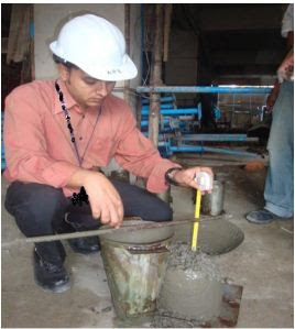
Slump test for Concrete used to determine the workability of concrete at construction site.

Apparatus:

Slump Test for Concrete


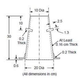
1) Slump Cone ( having diameter of 4" or 10 cm.  and 8" or 20 cm. also have a height of 12" or 30 cm.

Slump Test for Concrete

2) Measuring Scale
3) Temping Rod 16 mm diameter

Procedure:

1) The base should placed on a smooth surface and the cone will filled in three (03) layer with concrete.

2) Each layer have to temped 25 times with temping rod.

3) After filling the mould, excess concrete should be removed and the surface should be leveled. When the mould will filled fresh concrete, the base of the mould will held firmly by handles.

4)Then the mould will lifted gently in the vertical direction and then unsupported concrete will slump. The decrease in height at the center point is measured to nearest 5 mm or 0.25 inch and it is known as "slump". 

Slump Test for Concrete


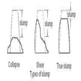
Types of Concrete Slump:

1) True Slump.
2) Collapse slump
3) Shear Slump

Slump Test for Concrete

You may like this: workability-of-concrete

Results Can be Classified With slump Values are as follows:

 Degree of Workability    


     Slump      


 Suitable to Use 


 Very Low 


 0-25

 
Used in Road work


 Low


 25-50


 Used in Foundation with light reinforcement
road vibrate by hand operated machine


 Medium 


 50-100


Used in normal reinforced concrete manually compacted
 and heavily reinforced section with vibrations.


 High

 
100-175


 Used in section with congested reinforcement.
Not normally suitable for compaction.


Advantages of Concrete Slump Test:

1.Slump test is very easy and simple. Even non-technical person can perform it in construction site without any problem.

2.This test does not require any special or costly equipment and not to send the sample at laboratory. It can be done in the construction area.

3.It is very essential to check batch to batch or hour to hour variation in the materials which will be fed into the mixer. Too high or too low slump is an indicator of unwanted workability of concrete and mixer operator gets an alarm to find a solution to remedy the problem.

4.Slump test does not demand a long-time period to get the result. We can obtain slump value within some minutes.


Limitations or Disadvantages of Concrete Slump Test:

1.It is unreliable for lean mixes. In a lean mix, a true slump may convert into shear or collapse easily. Widely variation can be found from one sample of lean mix and it can be a great confusion to determine the exact result.

2.It cannot differentiate in workability of stiff mixes as it shows zero slumps. In dry range, no difference can be detected between different mixes with different workability.
3.It is not exact measurement because slump bears no unique relation to workability. Even, for different types of aggregates, the same slump can be recorded for different workability.

4.For a specimen, more than one shape can be resulted confusing the correct result. If shear slump occurs, it may attain true slump in next test.

5.It is not suitable for concrete formed of aggregate higher than 40 mm.


Field Test of Brick

Brick is a very important construction material. So we need to some of its field test besides laboratory test. The field test of bricks are described here:

1) Color Test: Brick should be uniform in color, besides that it should be bright.


2) Nail Test: Take a piece of brick a try to mark on it. It will be difficult to make a mark on a good quality brick.

3) Sound Test: Take Two (02) piece of brick at hand and struck them with each-other, a good quality brick will produce clear metallic sound. someone can perform this test with a brick and a hammer also. 


4) T-Test: Take two piece of brick and make a T-shape and drop it from a height of 1.2-1.5 meter, good quality brick will not break.


These tests preliminary will help you to ensure good quality brick in construction site.